What is the induced current? Development of the lesson "Experiments of Faraday. Electromagnetic induction". Laboratory work "Investigation of the phenomenon of electromagnetic induction"
Occurrence in the conductor of EMF induction
If you place it in a conductor and move it so that during its movement it crosses the field lines of force, then a conductor will appear, called induction emf.
EMF of induction will occur in the conductor even if the conductor itself remains motionless, and the magnetic field moves, crossing the conductor with its lines of force.
If the conductor in which the induction EMF is induced is closed to any external circuit, then under the action of this EMF, a current will flow through the circuit, called induction current.
EMF induction phenomenon in a conductor when it is crossed by magnetic field lines is called electromagnetic induction.
Electromagnetic induction is the reverse process, i.e., the conversion of mechanical energy into electrical energy.
Phenomenon electromagnetic induction found widest application in . The device of various electrical machines is based on its use.
The magnitude and direction of the induction emf
Let us now consider what will be the magnitude and direction of the EMF induced in the conductor.
The magnitude of the EMF of induction depends on the number of field lines of force crossing the conductor per unit time, i.e., on the speed of the conductor in the field.
The magnitude of the induced emf is directly dependent on the speed of the conductor in a magnetic field.
The magnitude of the induced emf also depends on the length of that part of the conductor that is intersected by the field lines. The greater part of the conductor is crossed by the field lines, the greater the EMF is induced in the conductor. And, finally, the stronger the magnetic field, i.e., the greater its induction, the greater the EMF occurs in the conductor crossing this field.
So, the magnitude of the EMF of induction that occurs in the conductor when it moves in a magnetic field is directly proportional to the induction of the magnetic field, the length of the conductor and the speed of its movement.
This dependence is expressed by the formula E = Blv,
where E is the induction emf; B - magnetic induction; I - conductor length; v - the speed of the conductor.
It must be firmly remembered that in a conductor moving in a magnetic field, an EMF of induction occurs only if this conductor is crossed by magnetic field lines. If the conductor moves along the field lines of force, i.e., does not cross, but, as it were, slides along them, then no EMF is induced in it. Therefore, the above formula is valid only when the conductor moves perpendicular to the magnetic lines of force fields.
The direction of the induced emf (as well as the current in the conductor) depends on which direction the conductor is moving. To determine the direction of the induced emf, there is a rule right hand.
If you hold the palm of your right hand so that it includes the magnetic lines of force of the field, and the bent thumb would indicate the direction of movement of the conductor, then the extended four fingers would indicate the direction of the induced EMF and the direction of the current in the conductor.
Right hand rule
EMF of induction in the coil
We have already said that in order to create an EMF induction in a conductor, it is necessary to move either the conductor itself or the magnetic field in a magnetic field. In both cases, the conductor must be crossed by magnetic field lines, otherwise the EMF will not be induced. The induced EMF, and hence the induced current, can be obtained not only in a straight conductor, but also in a conductor wound into a coil.
When moving inside a permanent magnet, an EMF is induced in it due to the fact that the magnetic flux of the magnet crosses the turns of the coil, i.e., in exactly the same way as it was when a rectilinear conductor moved in the field of a magnet.
If the magnet is lowered into the coil slowly, then the emf that arises in it will be so small that the arrow of the device may not even deviate. If, on the contrary, the magnet is quickly introduced into the coil, then the deflection of the arrow will be large. This means that the magnitude of the induced EMF, and hence the current strength in the coil, depends on the speed of the magnet, that is, on how quickly the field lines cross the turns of the coil. If we now alternately introduce into the coil at the same speed, first a strong magnet, and then a weak one, then we can see that with a strong magnet, the arrow of the device will deviate by a larger angle. Means, the magnitude of the induced emf, and hence the current strength in the coil, depends on the magnitude of the magnetic flux of the magnet.
And, finally, if the same magnet is introduced at the same speed, first into the coil with a large number turns, and then with a much smaller one, then in the first case the arrow of the device will deviate by a larger angle than in the second. This means that the magnitude of the induced EMF, and hence the current strength in the coil, depends on the number of its turns. The same results can be obtained if an electromagnet is used instead of a permanent magnet.
The direction of the EMF of induction in the coil depends on the direction of movement of the magnet. How to determine the direction of the EMF of induction, says the law established by E. X. Lenz.
Lenz's law for electromagnetic induction
Any change in the magnetic flux inside the coil is accompanied by the appearance of an induction EMF in it, and the faster the magnetic flux penetrating the coil changes, the greater the EMF is induced in it.
If the coil in which the induction EMF is created is closed to an external circuit, then an induction current flows through its turns, creating a magnetic field around the conductor, due to which the coil turns into a solenoid. It turns out in such a way that a changing external magnetic field causes an induction current in the coil, which, in turn, creates its own magnetic field around the coil - the current field.
Studying this phenomenon, E. X. Lenz established a law that determines the direction of the induction current in the coil, and, consequently, the direction of the induction EMF. The induction emf that occurs in the coil when the magnetic flux changes in it creates a current in the coil in such a direction that the magnetic flux of the coil created by this current prevents a change in the extraneous magnetic flux.
Lenz's law is valid for all cases of current induction in conductors, regardless of the shape of the conductors and on how the change in the external magnetic field is achieved.

When a permanent magnet moves relative to a wire coil attached to the terminals of a galvanometer, or when the coil moves relative to a magnet, an induction current occurs.
Induction currents in massive conductors
A changing magnetic flux is capable of inducing an EMF not only in coil turns, but also in massive metal conductors. Penetrating the thickness of a massive conductor, the magnetic flux induces an EMF in it, which creates induction currents. These so-called ones propagate along the massive conductor and are short-circuited in it.
The cores of transformers, the magnetic circuits of various electrical machines and apparatuses are just those massive conductors that are heated by the induction currents that arise in them. This phenomenon is undesirable, therefore, in order to reduce the magnitude of induction currents, parts of electrical machines and transformer cores are made not massive, but consisting of thin sheets isolated from one another by paper or a layer of insulating varnish. Due to this, the path of propagation of eddy currents along the mass of the conductor is blocked.
But sometimes in practice eddy currents are also used as useful currents. The use of these currents is based, for example, on the operation of the so-called magnetic dampers of the moving parts of electrical measuring instruments.
The figure shows the direction of the inductive current that occurs in a short-circuited wire coil when the coil is moved relative to it.magnet. Please indicate which of the following statements are correct and which which are wrong.
A. The magnet and the coil are attracted to each other.
B. Inside the coil, the magnetic field of the induction current is directed upwards.
B. Inside the coil, the lines of magnetic induction of the field of the magnet are directed upwards.
D. The magnet is removed from the coil.
2. What frames of reference are inertial and non-inertial? Give examples.
3. What is the property of bodies called inertia? What is the value of inertia?
4. What is the relationship between the masses of bodies and the modules of accelerations that they receive during interaction?
5. What is strength and how is it characterized?
6. Statement of Newton's 2nd law? What is it mathematical notation?
7. How is Newton's 2nd law formulated in impulsive form? His math notation?
8. What is 1 Newton?
9. How does a body move if a force is applied to it that is constant in magnitude and direction? What is the direction of the acceleration caused by the force acting on it?
10. How is the resultant of forces determined?
11. How is Newton's 3rd law formulated and written down?
12. How are the accelerations of interacting bodies directed?
13. Give examples of the manifestation of Newton's 3rd law.
14. What are the limits of applicability of all Newton's laws?
15. Why can we consider the Earth as an inertial frame of reference if it moves with centripetal acceleration?
16. What is deformation, what types of deformation do you know?
17. What force is called the force of elasticity? What is the nature of this force?
18. What are the features of the elastic force?
19. How is the elastic force directed (support reaction force, thread tension force?)
20. How is Hooke's law formulated and written? What are its limits of applicability? Plot a graph illustrating Hooke's law.
21. How is the law of universal gravitation formulated and written down, when is it applicable?
22. Describe the experiments to determine the value of the gravitational constant?
23. What is the gravitational constant, what is its physical meaning?
24. Does the work of the gravitational force depend on the shape of the trajectory? What is the work done by gravity in a closed loop?
25. Does the work of the elastic force depend on the shape of the trajectory?
26. What do you know about gravity?
27. How acceleration is calculated free fall on Earth and other planets?
28. What is the first cosmic speed? How is it calculated?
29. What is called free fall? Does the acceleration of free fall depend on the mass of the body?
30. Describe the experience of Galileo Galilei, proving that all bodies in a vacuum fall with the same acceleration.
31. What force is called the force of friction? Types of friction forces?
32. How is the force of sliding and rolling friction calculated?
33. When does the static friction force arise? What is it equal to?
34. Does the force of sliding friction depend on the area of the contact surfaces?
35. On what parameters does the force of sliding friction depend?
36. What determines the force of resistance to the movement of a body in liquids and gases?
37. What is called body weight? What is the difference between the weight of a body and the force of gravity acting on a body?
38. In what case is the weight of the body numerically equal to the modulus of gravity?
39. What is weightlessness? What is overload?
40. How to calculate the weight of a body during its accelerated movement? Does the weight of a body change if it moves along a fixed horizontal plane with acceleration?
41. How does the weight of a body change when it moves along the convex and concave parts of the circle?
42. What is the algorithm for solving problems when a body moves under the action of several forces?
43. What force is called the Archimedes Force or the buoyant force? On what parameters does this force depend?
44. What formulas can be used to calculate the force of Archimedes?
45. Under what conditions does a body in a liquid float, sink, float?
46. How does the depth of immersion in a liquid of a floating body depend on its density?
47. Why Balloons filled with hydrogen, helium or hot air?
48. Explain the influence of the rotation of the Earth around its axis on the value of the acceleration of free fall.
49. How does the value of gravity change when: a) the removal of the body from the surface of the Earth, B) when the body moves along the meridian, parallel
electrical circuit?
3. What is the physical meaning of EMF? Define volt.
4. Connect to a short time voltmeter with a source of electrical energy, observing the polarity. Compare his readings with the calculation based on the results of the experiment.
5. What determines the voltage at the terminals of current sources?
6. Using the measurement results, determine the voltage on the external circuit (if the work was done by method I), the resistance of the external circuit (if the work was done by method II).
6 question in nesting calculation
Help me please!1. Under what conditions do friction forces appear?
2. What determines the modulus and direction of the static friction force?
3. Within what limits can the static friction force change?
4. What force imparts acceleration to a car or locomotive?
5. Can the force of sliding friction increase the speed of a body?
6. What is the main difference between the resistance force in liquids and gases and the friction force between two solid bodies?
7. Give examples of useful and harmful effect friction forces of all kinds
The relationship between electric and magnetic fields has been noticed for a very long time. This connection was discovered in the 19th century by the English physicist Faraday and gave it a name. It appears at the moment when the magnetic flux penetrates the surface of a closed circuit. After a change in the magnetic flux occurs for a certain time, an electric current appears in this circuit.
The relationship of electromagnetic induction and magnetic flux
The essence of the magnetic flux is displayed by the well-known formula: Ф = BS cos α. In it, F is a magnetic flux, S is the surface of the contour (area), B is the vector of magnetic induction. The angle α is formed due to the direction of the magnetic induction vector and the normal to the contour surface. It follows that the magnetic flux will reach the maximum threshold at cos α = 1, and the minimum threshold at cos α = 0.
In the second variant, the vector B will be perpendicular to the normal. It turns out that the flow lines do not cross the contour, but only slide along its plane. Therefore, the characteristics will be determined by the lines of the vector B that intersect the surface of the contour. For calculation, Weber is used as a unit of measurement: 1 wb \u003d 1v x 1s (volt-second). Another, smaller unit of measure is the maxwell (µs). It is: 1 wb \u003d 108 μs, that is, 1 μs \u003d 10-8 wb.
For research by Faraday, two wire spirals were used, isolated from each other and placed on a wooden coil. One of them was connected to an energy source, and the other to a galvanometer designed to record small currents. At that moment, when the circuit of the original spiral closed and opened, in the other circuit the arrow of the measuring device deviated.
Conducting research on the phenomenon of induction
In the first series of experiments, Michael Faraday inserted a magnetized metal bar into a coil connected to a current, and then pulled it out (Fig. 1, 2).
1  2
2 
When a magnet is placed in a coil connected to a measuring device, an inductive current begins to flow in the circuit. If the magnetic bar is removed from the coil, the induction current still appears, but its direction is already reversed. Consequently, the parameters of the induction current will be changed in the direction of the bar and depending on the pole with which it is placed in the coil. The strength of the current is affected by the speed of movement of the magnet.
In the second series of experiments, a phenomenon is confirmed in which a changing current in one coil causes an induction current in another coil (Fig. 3, 4, 5). This happens at the moments of closing and opening the circuit. The direction of the current will depend on whether the electrical circuit closes or opens. In addition, these actions are nothing more than ways to change the magnetic flux. When the circuit is closed, it will increase, and when it is opened, it will decrease, simultaneously penetrating the first coil.
3  4
4 
5 
As a result of the experiments, it was found that the occurrence of an electric current inside a closed conducting circuit is possible only when they are placed in an alternating magnetic field. At the same time, the flow can change in time by any means.
The electric current that appears under the influence of electromagnetic induction is called induction, although this will not be a current in the conventional sense. When a closed circuit is in a magnetic field, an EMF is generated with an exact value, and not a current depending on different resistances.
This phenomenon is called the EMF of induction, which is reflected by the formula: Eind = - ∆F / ∆t. Its value coincides with the rate of change in the magnetic flux penetrating the surface of a closed loop, taken from negative value. The minus present in this expression is a reflection of Lenz's rule.
Lenz's rule for magnetic flux
A well-known rule was derived after a series of studies in the 30s of the 19th century. It is formulated in the following way:
The direction of the induction current, excited in a closed circuit by a changing magnetic flux, affects the magnetic field it creates in such a way that it, in turn, creates an obstacle to the magnetic flux, causing the appearance induction current.

When the magnetic flux increases, that is, it becomes Ф > 0, and the induction EMF decreases and becomes Eind< 0, в результате этого появляется электроток с такой направленностью, при которой под влиянием его магнитного поля происходит изменение потока в сторону уменьшения при его прохождении через плоскость замкнутого контура.
If the flow decreases, then the reverse process occurs when F< 0 и Еинд >0, that is, the action of the magnetic field of the induction current, there is an increase in the magnetic flux passing through the circuit.
The physical meaning of Lenz's rule is to reflect the law of conservation of energy, when when one quantity decreases, the other increases, and, conversely, when one quantity increases, the other will decrease. Various factors also affect the induction emf. When a strong and weak magnet is alternately inserted into the coil, the device will respectively show a higher value in the first case, and a lower value in the second. The same thing happens when the speed of the magnet changes.

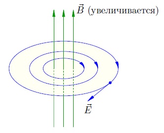
The figure below shows how the direction of the induction current is determined using the Lenz rule. Blue colour corresponds to the lines of force of the magnetic fields of the induction current and the permanent magnet. They are located in the direction of the north-south poles that are present in every magnet.
The changing magnetic flux leads to the emergence of an inductive electric current, the direction of which causes opposition from its magnetic field, which prevents changes in the magnetic flux. In this regard, the lines of force of the magnetic field of the coil are directed in the direction opposite to the lines of force of the permanent magnet, since its movement occurs in the direction of this coil.
To determine the direction of the current, it is used with a right-hand thread. It must be screwed in in such a way that the direction of its forward movement coincides with the direction of the induction lines of the coil. In this case, the directions of the induction current and the rotation of the gimlet handle will coincide.
As we have already found out, electricity capable of generating magnetic fields. The question arises: can a magnetic field cause the appearance of an electric current? This problem was solved by the English physicist Michael Faraday, who discovered the phenomenon of electromagnetic induction in 1831. A coiled conductor closes on a galvanometer (Fig. 3.19). If a permanent magnet is pushed into the coil, the galvanometer will show the presence of current for the entire time period while the magnet is moving relative to the coil. When the magnet is pulled out of the coil, the galvanometer shows the presence of a current in the opposite direction. A change in the direction of the current occurs when the retractable or retractable pole of the magnet changes.
Similar results were observed when replacing a permanent magnet with an electromagnet (coil with current). If both coils are fixed motionless, but the current value is changed in one of them, then at this moment an induction current is observed in the other coil.
THE PHENOMENON OF ELECTROMAGNETIC INDUCTION consists in the occurrence of an electromotive force (emf) of induction in a conducting circuit, through which the flux of the magnetic induction vector changes. If the circuit is closed, then an induction current arises in it.
Discovery of the phenomenon of electromagnetic induction:
1) showed relationship between electrical and magnetic field ;
2) suggested method of generating electric current using a magnetic field.
Main properties of induction current:
1. Induction current always occurs when there is a change in the flux of magnetic induction coupled to the circuit.
2. The strength of the induction current does not depend on the method of changing the flux of magnetic induction, but is determined only by the rate of its change.
Faraday's experiments found that the magnitude of the electromotive force of induction is proportional to the rate of change of the magnetic flux penetrating the conductor circuit (Faraday's law of electromagnetic induction)
Or , (3.46)
where (dF) is the change in flux over time (dt). MAGNETIC FLUX or FLOW OF MAGNETIC INDUCTION is called the value, which is determined on the basis of the following relation: ( magnetic flux through a surface area S): Ф=ВScosα, (3.45), angle a is the angle between the normal to the surface under consideration and the direction of the magnetic field induction vector
unit of magnetic flux in the SI system is called weber- [Wb \u003d Tl × m 2].
The sign "-" in the formula means that the emf. induction causes an induction current, the magnetic field of which counteracts any change in the magnetic flux, i.e. at >0 e.m.f. induction e AND<0 и наоборот.
emf induction is measured in volts
To find the direction of the induction current, there is Lenz's rule (the rule was established in 1833): the induction current has such a direction that the magnetic field it creates tends to compensate for the change in the magnetic flux that caused this induction current.
For example, if you push the north pole of the magnet into the coil, that is, increase the magnetic flux through its turns, an induction current arises in the coil in such a direction that a north pole appears at the end of the coil closest to the magnet (Fig. 3.20). So, the magnetic field of the induction current tends to neutralize the change in the magnetic flux that caused it.
 Not only an alternating magnetic field generates an induction current in a closed conductor, but also when a closed conductor of length l moves in a constant magnetic field (B) at a speed v, an emf arises in the conductor:
![]() a (B Ùv) (3.47)
a (B Ùv) (3.47)
As you already know, electromotive force in the chain is the result of external forces. When the conductor moves in a magnetic field, the role of external forces performs Lorentz force(which acts from the side of the magnetic field on a moving electric charge). Under the action of this force, a separation of charges occurs and a potential difference arises at the ends of the conductor. emf induction in a conductor is the work of moving unit charges along the conductor.
Direction of induction current can be determined according to the right hand rule:Vector B enters the palm, the abducted thumb coincides with the direction of the conductor's velocity, and 4 fingers indicate the direction of the induction current.
Thus, an alternating magnetic field causes the appearance of an induced electric field. It not potentially(as opposed to electrostatic), because Work by the displacement of a single positive charge equal to emf. induction, not zero.
Such fields are called vortex. The lines of force of the vortex electric field - locked in on themselves as opposed to lines of tension electrostatic field.
emf induction occurs not only in neighboring conductors, but also in the conductor itself when the magnetic field of the current flowing through the conductor changes. Emf occurrence. in any conductor, when the current strength changes in it (hence, the magnetic flux in the conductor) is called self-induction, and the current induced in this conductor is self-induction current.
The current in a closed circuit creates a magnetic field in the surrounding space, the strength of which is proportional to the strength of the current I. Therefore, the magnetic flux Ф penetrating the circuit is proportional to the strength of the current in the circuit
Ф=L×I, (3.48).
L is the coefficient of proportionality, which is called the coefficient of self-induction, or, simply, inductance. The inductance depends on the size and shape of the circuit, as well as on the magnetic permeability of the medium surrounding the circuit.
In this sense, the inductance of the circuit - analogue the electric capacitance of a solitary conductor, which also depends only on the shape of the conductor, its dimensions and the permittivity of the medium.
The unit of inductance is henry (H): 1H - the inductance of such a circuit, the magnetic flux of self-induction of which at a current of 1A is 1Wb (1Hn \u003d 1Wb / A \u003d 1V s / A).
If L=const, then emf. self-induction can be represented in the following form:
![]() , or
, or ![]() , (3.49)
, (3.49)
where DI (dI) is the change in current in the circuit containing the inductor (or circuit) L, during the time Dt (dt). The sign "-" in this expression means that the emf. self-induction prevents a change in current (i.e., if the current in a closed circuit decreases, then the emf of self-induction leads to a current in the same direction and vice versa).
One of the manifestations of electromagnetic induction is the occurrence of closed induction currents in continuous conductive media: metallic bodies, electrolyte solutions, biological organs, etc. Such currents are called eddy currents or Foucault currents. These currents arise when a conducting body moves in a magnetic field and/or when the induction of the field in which the bodies are placed changes with time. The strength of the Foucault currents depends on the electrical resistance of the bodies, as well as on the rate of change of the magnetic field.
Foucault currents also obey Lenz's rule : their magnetic field is directed so as to counteract the change in magnetic flux that induces eddy currents.
Therefore, massive conductors are decelerated in a magnetic field. In electrical machines, in order to minimize the effect of Foucault currents, the cores of transformers and the magnetic circuits of electrical machines are assembled from thin plates isolated from each other by a special varnish or scale.
Eddy currents cause strong heating of conductors. Joule heat generated by Foucault currents, used in induction metallurgical furnaces for melting metals, according to the Joule-Lenz law.
Topics of the USE codifier Keywords: phenomenon of electromagnetic induction, magnetic flux, Faraday's law of electromagnetic induction, Lenz's rule.
Oersted's experiment showed that electric current creates a magnetic field in the surrounding space. Michael Faraday came up with the idea that there could be an opposite effect: the magnetic field, in turn, generates an electric current.
In other words, let there be a closed conductor in a magnetic field; Will there not be an electric current in this conductor under the influence of a magnetic field?
After ten years of searching and experimenting, Faraday finally succeeded in discovering this effect. In 1831 he set up the following experiments.
1. Two coils were wound on the same wooden base; the turns of the second coil were laid between the turns of the first and insulated. The outputs of the first coil were connected to a current source, the outputs of the second coil were connected to a galvanometer (a galvanometer is a sensitive device for measuring small currents). Thus, two circuits were obtained: "current source - first coil" and "second coil - galvanometer".
There was no electrical contact between the circuits, only the magnetic field of the first coil penetrated the second coil.
When the circuit of the first coil was closed, the galvanometer recorded a short and weak current pulse in the second coil.
When a direct current flowed through the first coil, no current was generated in the second coil.
When the circuit of the first coil was opened, a short and weak current pulse again appeared in the second coil, but this time in the opposite direction compared to the current when the circuit was closed.
Conclusion.
The time-varying magnetic field of the first coil generates (or, as they say, induces) electric current in the second coil. This current is called by induction current.
If the magnetic field of the first coil increases (at the moment the current rises when the circuit is closed), then the induction current in the second coil flows in one direction.
If the magnetic field of the first coil decreases (at the moment the current decreases when the circuit is opened), then the induction current in the second coil flows in the other direction.
If the magnetic field of the first coil does not change (a constant current through it), then there is no induction current in the second coil.
Faraday called the discovered phenomenon electromagnetic induction(i.e. "induction of electricity by magnetism").
2. To confirm the conjecture that the induction current is generated variables magnetic field, Faraday moved the coils relative to each other. The circuit of the first coil remained closed all the time, a direct current flowed through it, but due to movement (approach or removal), the second coil found itself in an alternating magnetic field of the first coil.
The galvanometer again recorded the current in the second coil. The induction current had one direction when the coils approached, and the other - when they were removed. In this case, the strength of the induction current was the greater, the faster the coils moved.
3. The first coil has been replaced by a permanent magnet. When a magnet was introduced into the second coil, an induction current arose. When the magnet was pulled out, the current appeared again, but in the other direction. And again, the strength of the induction current was the greater, the faster the magnet moved.
These and subsequent experiments showed that an induction current in a conducting circuit occurs in all those cases when the "number of lines" of the magnetic field penetrating the circuit changes. The strength of the induction current is the greater, the faster this number of lines changes. The direction of the current will be one with an increase in the number of lines through the circuit, and the other - with a decrease in them.
It is remarkable that for the magnitude of the current strength in a given circuit, only the rate of change in the number of lines is important. What exactly happens in this case does not play a role - whether the field itself, penetrating the fixed contour, changes, or the contour moves from an area with one density of lines to an area with another density.
This is the essence of the law of electromagnetic induction. But in order to write a formula and make calculations, you need to clearly formalize the vague concept of "the number of field lines through the contour."
magnetic flux
The concept of magnetic flux is just a characteristic of the number of magnetic field lines penetrating the circuit.
For simplicity, we restrict ourselves to the case of a uniform magnetic field. Let us consider the contour of the area, located in a magnetic field with induction.
First, let the magnetic field be perpendicular to the contour plane (Fig. 1).

Rice. one.
In this case, the magnetic flux is determined very simply - as the product of the magnetic field induction and the area of \u200b\u200bthe circuit:
(1)
Now consider the general case when the vector forms an angle with the normal to the contour plane (Fig. 2).

Rice. 2.
We see that now only the perpendicular component of the magnetic induction vector “flows” through the circuit (and the component that is parallel to the circuit does not “flow” through it). Therefore, according to formula (1), we have . But, therefore
(2)
This is the general definition of magnetic flux in the case of a uniform magnetic field. Note that if the vector is parallel to the contour plane (i.e. ), then the magnetic flux becomes zero.
And how to determine the magnetic flux if the field is not uniform? Let's just give an idea. The contour surface is divided into a very large number of very small areas, within which the field can be considered homogeneous. For each site, we calculate our own small magnetic flux using the formula (2), and then we summarize all these magnetic fluxes.
The unit of magnetic flux is weber(Wb). As we see,
Wb \u003d Tl m \u003d V s. (3)
Why does the magnetic flux characterize the "number of lines" of the magnetic field penetrating the circuit? Very simple. The "number of lines" is determined by their density (and hence by the value - after all, the greater the induction, the thicker the lines) and the "effective" area permeated by the field (and this is nothing more than ). But the multipliers just form the magnetic flux!
Now we can give a clearer definition of the phenomenon of electromagnetic induction discovered by Faraday.
Electromagnetic induction- this is the phenomenon of the occurrence of an electric current in a closed conducting circuit when the magnetic flux penetrating the circuit changes.
EMF induction
What is the mechanism of induction current occurrence? We will discuss this later. So far, one thing is clear: when the magnetic flux passing through the circuit changes, some forces act on the free charges in the circuit - outside forces that cause charges to move.
As we know, the work of external forces to move a unit positive charge around the circuit is called electromotive force (EMF):. In our case, when the magnetic flux through the circuit changes, the corresponding EMF is called EMF induction and is denoted.
So, EMF of induction is the work of external forces that arise when the magnetic flux through the circuit changes, to move a unit positive charge around the circuit.
We will soon find out the nature of the extraneous forces that arise in this case in the circuit.
Faraday's law of electromagnetic induction
The strength of the induction current in Faraday's experiments turned out to be the greater, the faster the magnetic flux through the circuit changed.
If in a short time the change in the magnetic flux is , then speed the change in magnetic flux is a fraction (or, equivalently, the derivative of the magnetic flux with respect to time).
Experiments have shown that the strength of the induction current is directly proportional to the modulus of the rate of change of the magnetic flux:
The module was installed in order not to contact negative values for the time being (after all, when the magnetic flux decreases, it will be ). Later we will remove this module.
From Ohm's law for a complete chain, we at the same time have: . Therefore, the induction emf is directly proportional to the rate of change of the magnetic flux:
(4)
EMF is measured in volts. But the rate of change of magnetic flux is also measured in volts! Indeed, from (3) we see that Wb / s = V. Therefore, the units of measurement of both parts of proportionality (4) are the same, therefore the proportionality coefficient is a dimensionless quantity. In the SI system, it is assumed to be equal to one, and we get:
(5)
That's what it is law of electromagnetic induction or Faraday's law. Let's give it a verbal formulation.
Faraday's law of electromagnetic induction. When the magnetic flux penetrating the circuit changes, an induction emf arises in this circuit, equal to the modulus of the rate of change of the magnetic flux.
Lenz's rule
The magnetic flux, the change of which leads to the appearance of an induction current in the circuit, we will call external magnetic flux. And the magnetic field itself, which creates this magnetic flux, we will call external magnetic field.
Why do we need these terms? The fact is that the induction current that occurs in the circuit creates its own own a magnetic field that, according to the principle of superposition, is added to an external magnetic field.
Accordingly, along with the external magnetic flux, own the magnetic flux created by the magnetic field of the induction current.
It turns out that these two magnetic fluxes - own and external - are interconnected in a strictly defined way.
Lenz's rule. The induction current always has such a direction that its own magnetic flux prevents a change in the external magnetic flux.
Lenz's rule allows you to find the direction of the induction current in any situation.
Consider some examples of applying the Lenz rule.
Let us assume that the circuit is penetrated by a magnetic field, which increases with time (Fig. (3)). For example, we bring a magnet closer to the contour from below, the north pole of which is directed upwards in this case, to the contour.
The magnetic flux through the circuit increases. The induction current will have such a direction that the magnetic flux it creates prevents an increase in the external magnetic flux. To do this, the magnetic field created by the induction current must be directed against external magnetic field.
The inductive current flows counterclockwise when viewed from the side of the magnetic field it creates. In this case, the current will be directed clockwise when viewed from above, from the side of the external magnetic field, as shown in (Fig. (3)).

Rice. 3. Magnetic flux increases
Now suppose that the magnetic field penetrating the circuit decreases with time (Fig. 4). For example, we are moving the magnet down from the loop, and the north pole of the magnet is facing the loop.

Rice. 4. Magnetic flux decreases
The magnetic flux through the circuit decreases. The inductive current will have such a direction that its own magnetic flux supports the external magnetic flux, preventing it from decreasing. To do this, the magnetic field of the induction current must be directed in the same direction, which is the external magnetic field.
In this case, the inductive current will flow counterclockwise when viewed from above, from the side of both magnetic fields.
The interaction of the magnet with the circuit
So, the approach or removal of the magnet leads to the appearance of an induction current in the circuit, the direction of which is determined by the Lenz rule. But the magnetic field acts on the current! The Ampere force will appear, acting on the circuit from the side of the magnet field. Where will this force be directed?
If you want a good understanding of Lenz's rule and determining the direction of the Ampère force, try to answer this question yourself. This is not a very simple exercise and an excellent task for C1 in the exam. Consider four possible cases.
1. We bring the magnet closer to the contour, the north pole is directed to the contour.
2. We remove the magnet from the contour, the north pole is directed to the contour.
3. We bring the magnet closer to the contour, the south pole is directed to the contour.
4. We remove the magnet from the circuit, the south pole is directed to the circuit.
Do not forget that the field of a magnet is not uniform: the field lines diverge from the north pole and converge towards the south. This is very essential for determining the resulting Ampère force. The result is the following.
If you bring the magnet closer, then the contour is repelled from the magnet. If you remove the magnet, the circuit is attracted to the magnet. Thus, if the circuit is suspended on a thread, then it will always deviate in the direction of the movement of the magnet, as if following it. The location of the poles of the magnet does not matter..
In any case, you should remember this fact - suddenly such a question comes across in part A1
This result can also be explained from quite general considerations - with the help of the law of conservation of energy.
Let's say we bring the magnet closer to the contour. An inductive current appears in the circuit. But to create a current, work must be done! Who is doing it? Ultimately - we, moving the magnet. We perform positive mechanical work, which is converted into positive work of external forces that arise in the circuit and create an induction current.
So our job of moving the magnet should be positive. This means that we, approaching the magnet, must overcome the force of interaction of the magnet with the circuit, which, therefore, is the force repulsion.
Now remove the magnet. Please repeat these considerations and make sure that an attractive force should arise between the magnet and the circuit.
Faraday's Law + Lenz's Rule = Module Removal
Above, we promised to remove the modulus in Faraday's law (5) . Lenz's rule allows you to do this. But first, we will need to agree on the sign of the induction EMF - after all, without the module on the right side of (5), the EMF value can be both positive and negative.
First of all, one of the two possible directions for bypassing the contour is fixed. This direction is announced positive. The opposite direction of traversing the contour is called, respectively, negative. Which direction we take as a positive bypass does not matter - it is only important to make this choice.
The magnetic flux through the circuit is considered positive class="tex" alt="(!LANG:(\Phi > 0)"> !}, if the magnetic field penetrating the circuit is directed there, looking from where the circuit is bypassed in a positive direction counterclockwise. If, from the end of the magnetic induction vector, the positive bypass direction is seen clockwise, then the magnetic flux is considered negative.
EMF of induction is considered positive class="tex" alt="(!LANG:(\mathcal E_i > 0)"> !} if the inductive current flows in the positive direction. In this case, the direction of external forces arising in the circuit when the magnetic flux through it changes coincides with the positive direction of the circuit bypass.
Conversely, the induction emf is considered negativeif the inductive current flows in a negative direction. Third-party forces in this case will also act along the negative direction of bypassing the contour.
So, let the circuit be in a magnetic field. We fix the direction of the positive bypass of the contour. Let's assume that the magnetic field is directed there, looking from where the positive bypass is made counterclockwise. Then the magnetic flux is positive: class="tex" alt="(!LANG:\Phi > 0"> .!}

Rice. 5. Magnetic flux increases
So, in this case, we have . The sign of the induction EMF turned out to be opposite to the sign of the rate of change of the magnetic flux. Let's check this in another situation.
Namely, suppose now that the magnetic flux decreases. According to Lenz's law, the induced current will flow in the positive direction. That is, class="tex" alt="(!LANG:\mathcal E_i > 0"> !}(Fig. 6).

Rice. 6. Magnetic flux increases class="tex" alt="(!LANG:\Rightarrow \mathcal E_i > 0"> !}
Such is the reality general fact: with our agreement on signs, the Lenz rule always leads to the fact that the sign of the induction emf is opposite to the sign of the rate of change of the magnetic flux:
(6)
Thus, the sign of the modulus in Faraday's law of electromagnetic induction has been eliminated.
Vortex electric field
Let us consider a motionless circuit located in an alternating magnetic field. What is the mechanism of occurrence of inductive current in the circuit? Namely, what forces cause the movement of free charges, what is the nature of these extraneous forces?
In trying to answer these questions, the great English physicist Maxwell discovered a fundamental property of nature: time-varying magnetic field generates an electric field. It is this electric field that acts on free charges, causing an induction current.
The lines of the emerging electric field turn out to be closed, in connection with which it was called vortex electric field. The lines of the vortex electric field go around the lines of the magnetic field and are directed as follows.
Let the magnetic field increase. If there is a conducting circuit in it, then the induction current will flow in accordance with Lenz's rule - clockwise, when viewed from the end of the vector. This means that the force acting from the side of the vortex electric field on the positive free charges of the circuit is also directed there; this means that the vector of the vortex electric field strength is directed exactly there.
So, the lines of the vortex electric field are directed in this case clockwise (we look from the end of the vector, (Fig. 7).
Rice. 7. Vortex electric field with increasing magnetic field
On the contrary, if the magnetic field decreases, then the lines of the vortex electric field strength are directed counterclockwise (Fig. 8).

Rice. 8. Vortex electric field with decreasing magnetic field
Now we can better understand the phenomenon of electromagnetic induction. Its essence lies precisely in the fact that an alternating magnetic field generates a vortex electric field. This effect does not depend on whether there is a closed conducting circuit in the magnetic field or not; with the help of a circuit, we only detect this phenomenon by observing the induction current.
The vortex electric field differs in some properties from the electric fields already known to us: the electrostatic field and the stationary field of charges that form a direct current.
1. The lines of the vortex field are closed, while the lines of the electrostatic and stationary fields start on positive charges and end on negative ones.
2. The vortex field is non-potential: its work to move the charge along a closed circuit is not equal to zero. Otherwise, the vortex field could not create an electric current! At the same time, as we know, electrostatic and stationary fields are potential.
So, The induction emf in a fixed circuit is the work of a vortex electric field to move a single positive charge around the circuit.
Let, for example, the contour be a ring of radius and be penetrated by a uniform alternating magnetic field. Then the strength of the vortex electric field is the same at all points of the ring. The work of the force with which the vortex field acts on the charge is equal to:
Therefore, for the induction EMF we get:
EMF of induction in a moving conductor
If the conductor moves in a constant magnetic field, then an EMF of induction also appears in it. However, now the cause is not the vortex electric field (it does not arise - after all, the magnetic field is constant), but the action of the Lorentz force on the free charges of the conductor.
Consider a situation that often occurs in problems. Parallel rails are located in the horizontal plane, the distance between them is equal to . The rails are in a vertical uniform magnetic field. A thin conducting rod moves along the rails at a speed it always remains perpendicular to the rails ( fig. 9).

Rice. 9. Movement of a conductor in a magnetic field
Let us take a positive free charge inside the rod. Due to the movement of this charge together with the rod at a speed, the Lorentz force will act on the charge:
This force is directed along the axis of the rod, as shown in the figure (see for yourself - do not forget the rule of the hour hand or the left hand!).
The Lorentz force in this case plays the role of an outside force: it sets the free charges of the rod in motion. When moving a charge from point to point, our third-party force will do the work:
(We also consider the length of the rod equal.) Therefore, the induction emf in the rod will be equal to:
(7)
Thus, the rod is similar to a current source with a positive terminal and a negative terminal. Inside the rod, due to the action of the external Lorentz force, the charges are separated: positive charges move towards the point , negative charges move towards the point .
Let us first assume that the rails do not conduct current. Then the movement of charges in the rod will gradually stop. After all, as positive charges accumulate at the end and negative charges at the end, the Coulomb force will increase, with which the positive free charge is repelled from and attracted to - and at some point this Coulomb force will balance the Lorentz force. A potential difference is established between the ends of the rod, equal to EMF induction (7) .
Now suppose that the rails and the jumper are conductive. Then an induction current will appear in the circuit; it will go in the direction (from "source plus" to "minus" N). Suppose that the resistance of the rod is equal (this is an analogue of the internal resistance of the current source), and the resistance of the section is equal (the resistance of the external circuit). Then the strength of the induction current can be found according to Ohm's law for a complete circuit:
It is remarkable that expression (7) for the induction emf can also be obtained using Faraday's law. Let's do it.
During the time, our rod travels a path and occupies a position (Fig. 9). The area of the contour increases by the area of the rectangle:
The magnetic flux through the circuit increases. The increment of the magnetic flux is:
The rate of change of the magnetic flux is positive and equal to the EMF of induction:
We got the same result as in (7) . The direction of the induction current, we note, obeys the Lenz rule. Indeed, since the current flows in the direction , then its magnetic field is directed opposite to the external field and, therefore, prevents the increase in the magnetic flux through the circuit.
In this example, we see that in situations where the conductor moves in a magnetic field, it is possible to act in two ways: either with the involvement of the Lorentz force as an external force, or with the help of Faraday's law. The results will be the same.