Power supply load calculation calculator. Calculation of electrical loads of apartments and cottages. Calculation of short circuit currents. Method of specific load densities
The article is intended for those who have a high school knowledge of electrical engineering and want to become familiar with the application of electrical calculations in some cases of everyday life. Please write your feedback and suggestions for adding other calculations in the comments.
1. Calculation of the magnitude of alternating electric current with a single-phase load.
Let's assume that we have an ordinary house or apartment in which there is an alternating current electrical network with a voltage of 220 volts.
The house has electrical appliances:
1. To illuminate the house, 5 light bulbs of 100 watts each and 8 light bulbs of 60 watts each are installed. 2. Electric oven, power 2 kilowatts or 2000 watts. 3. TV with a power of 0.1 kilowatt or 100 watts. 4. Refrigerator with a capacity of 0.3 kilowatts or 300 watts. 5. Washing machine with a power of 0.6 kilowatts or 600 watts. We are interested in what current will flow at the input to our house or apartment when all of the above electrical appliances are operating simultaneously and whether our electric meter, designed for a current of 20 amperes, will be damaged?
Calculation: 1. Determine the total power of all devices: 500 + 480 + 2000 + 100 + 300 + 600 = 3980 watts 2. The current flowing in the wire at this power is determined by the formula:

Where: I - current in amperes (A) P - power in watts (W) U - voltage in volts (V) cos φ - power factor (for household electrical networks you can take 0.95) Substitute the numbers into the formula: I = 3980 / 220 * 0.95 = 19.04 A Conclusion: The meter will withstand, since the current in the circuit is less than 20 A. For the convenience of users, a current calculation form is given below.
You should enter in the appropriate fields of the form the total power value in watts of all your electrical appliances, voltage in volts, usually 220 and power factor, 0.95 for household loads, click the "Calculate" button and the current value in amperes will appear in the "Current" field. If you have a load in kilowatts, you should convert it to watts by multiplying by 1000. To clear the entered power value, click the "Clear" button. Clearing the default voltage and cosine values should be done by pressing the delete key and moving the cursor to the appropriate cell (if necessary).
Calculation form for determining the current for a single-phase load.
The same calculation can be performed for a retail outlet, garage or any facility that has a single-phase input. But what if we know the current, which we determined using a current clamp or an ammeter, but we need to know the connected power?
![]()
Calculation form for determining power for a single-phase load.
What is the value of cos φ for other pantographs?(Attention! The values of cosine phi for your equipment may differ from those indicated): Incandescent lamps and electric heating devices with resistance heating (cosφ ≈ 1.0) Asynchronous motors, at partial load (cosφ ≈ 0.5) Rectifier electrolysis units (cosφ ≈ 0 .6) Electric arc furnaces (cosφ ≈ 0.6) Induction furnaces (cosφ ≈ 0.2-0.6) Water pumps (cosφ ≈ 0.8) Compressors (cosφ ≈ 0.7) Machines, machine tools (cosφ ≈ 0, 5) Welding transformers (cosφ ≈ 0.4) Fluorescent lamps connected via an electromagnetic choke (cosφ ≈ 0.5-0.6)
2. Calculation of the magnitude of direct electric current.
Direct current for everyday life is used mainly in electronic devices, as well as in the on-board electrical network of a car. Let's say you decide to install an additional headlight in a car with a 60-watt lamp and connect it from the low beam headlight. And the question immediately arises - will the existing 10 amp fuse for the low beam headlight hold when connecting another headlight?

Calculation: Let's assume that the power of the low beam headlight bulb is 65 watts. Let's calculate the current using the formula:
where: I - current in amperes (A) P - power in watts (W) U - voltage in volts (V)
As we see, unlike the formula for alternating current - cos φ - is not here. Let's substitute the numbers into the formula: I = 65 /12 = 5.42 A 65 W - lamp power 12 V - voltage in the vehicle's on-board network 5.42 A - current in the lamp circuit. The power of two lamps in the main and additional headlights will be 60 + 65 = 125 W I = 125/12 = 10.42 A Conclusion: When connecting 2 headlights, a fuse rated at 10 A may not withstand it, so it is advisable to replace it with the nearest one with a high setting current. Before replacement, it is necessary to check the value of the continuous permissible current for the wire of this circuit, and the fuse tripping current must be less than the continuous permissible current of the wire.
For the convenience of users, a current calculation form is given below. You should enter in the appropriate fields of the form the total power value in watts of all your electrical appliances, the voltage in volts, click the "Calculate" button and the current value in amperes will appear in the "Current" field. To clean, click the "Clear" button. Calculation form for determining direct current.
3. Calculation of the magnitude of alternating electric current with a three-phase load.
Now let's assume that we have an ordinary house or apartment in which there is an alternating current electrical network with a voltage of 380/220 volts. Why are two voltages indicated - 380 V and 220 V? The fact is that when connected to a three-phase network, 4 wires enter your house - 3 phases and a neutral (in the old way - zero).
So, the voltage between the phase wires or otherwise - the linear voltage will be 380 V, and between any of the phases and the neutral or otherwise the phase voltage will be 220 V. Each of the three phases has its own designation in the Latin letters A, B, C. The neutral is designated by the Latin N .
Thus, between phases A and B, A and C, B and C - there will be a voltage of 380 V. Between A and N, B and N, C and N there will be 220 V and electrical appliances with a voltage of 220 V can be connected to these wires, which means the house can have both three-phase and single-phase loads.
Most often, there is both and it is called a mixed load.
First, let's calculate the current for a purely three-phase load.
The house has three-phase electrical appliances:
1. Electric motor with a power of 3 kilowatts or 3000 watts.
2. Electric water heater with a power of 15 kilowatts or 15,000 watts.
In fact, three-phase loads are usually counted in kilowatts, therefore, if they are written in watts, they should be divided by 1000. We are interested in what current will flow at the input to our house or apartment when all of the above electrical appliances are operating simultaneously and whether our electric meter will be damaged rated for 20 amperes?
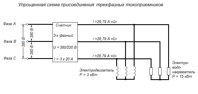
Calculation: We determine the total power of all devices: 3 kW + 15 kW = 18 kW 2. The current flowing in the phase wire at this power is determined by the formula:
![]()
Where: I - current in amperes (A) P - power in kilowatts (kW) U - linear voltage, V cos φ - power factor (for household electrical networks you can take 0.95) Substitute the numbers into the formula: = 28.79 A
Conclusion: The meter will not withstand it, so it needs to be replaced with a current of at least 30 A. For the convenience of users, a current calculation form is given below.
In order not to use a calculator, simply enter your numbers in the form below and press the "Calculate" button.
Calculation form for determining the current for a three-phase load.
But what to do when we know the current of the three-phase load (the same for each phase), which we determined using a current clamp or an ammeter, but we need to know the connected power?
Let's transform the formula for calculating current into calculating power.
![]()
In order not to use a calculator, simply enter your numbers in the form below and press the "Calculate" button.
Calculation form for determining power for a three-phase load.
Now let's calculate the current for mixed three-phase and single-phase loads.
So, 3 phases are installed in the house and the electrician installing the electrical wiring must strive to ensure that the phases are loaded evenly, although this is not always the case.
In our house it turned out, for example, like this: - phase A and neutral with the voltage between them, as we already know - 220 V is supplied to the garage and well, as well as yard lighting, total load - 12 light bulbs of 100 watts, electric pump 0.7 kW or 700 watts. - phase B and neutral with a voltage between them - 220 V are brought into the house, the total load is 1800 watts. - phase C and neutral with a voltage between them of 220 V are brought into the summer kitchen, the total load of the electric stove and lamps is 2.2 kW.
We have single-phase loads: phase A load is 1900 watts, phase B - 1800 watts, phase C - 2200 watts, a total of three phases 5.9 kW. In addition, the diagram shows three-phase loads of 3 kW and 15 kW, which means the total power of the mixed load will be 23.9 kW.

We enter the values of these powers one by one and calculate the currents.
For phase A it will be - 9.09 A, for B - 8.61 A, for C - 10.53 A. But we already have a three-phase load current passing through the wires of all three phases, therefore, in order to find out the total value of the current in each of phases, you just need to add the currents of three-phase and single-phase loads. Phase A 28.79 A + 9.09 A = 37.88 A Phase B 28.79 A + 8.61 = 37.40 A Phase C 28.79 A + 10.53 = 39.32 A. Highest mixed current load in phase C.
But what to do when we know the current of a mixed three-phase load (different for each phase), which we determined using a current clamp or an ammeter, and we need to know the connected power?
In this case, it is necessary to determine the power consumption of each of the three phases using the calculation form for determining the power for a single-phase load and then simply add these powers, which will give us the total power of the mixed three-phase load. Using the example for a mixed load, we see that the total current in phase A was 37.88 A, phase B - 37.40 A, phase C - 39.32 A.
7.2. Checking the selected section for voltage loss.
To begin with, from the known connected power P = 3980 W, phase voltage U f = 220 V and cosine phi 0.95, you need to determine the load current. I will not repeat myself, since we already covered this at the beginning of section 1. “Calculation of the magnitude of alternating electric current for a single-phase load.” In addition, to select the material and cross-section of the wire, it is necessary to add a safety factor of 30% to the load current or, which is the same thing, multiply by 1.3. In our case, the load current is 19.04 A. The safety factor is 30% of the load current 1.3 · I n = 1.3 · 19.04 = 24.76 A.
We select an aluminum wire and, according to Table 1.3.5 of the PUE, determine the nearest largest cross-section, which will be equal to 4 mm 2 for openly laid wires at a current of 32 A.
In order for the user to substitute their values, a calculation form consisting of two parts is given below.
Calculation form for determining voltage losses in a two-wire single-phase or two-phase network.
Part 1. Calculate the load current and current with a safety factor of 30% to select the wire cross-section.
Commercial metering of electrical energy Commercial metering of electrical energy (power) - the process of measuring the amount of electrical energy for the purposes of mutual settlements for supplied electrical energy and power, as well as for services related to these supplies;
Calculation of electrical loads
Calculation of electrical loads- the document below reflects the calculated values (active, reactive and apparent power, calculated current) for the main nodes of the facility’s electrical network. The calculation is performed for the following network nodes:
. switchgears 0.4 kV TP
. input devices (main switchboard, ASU)
. distribution boards
. group shields
Based on the calculated data, electrical network elements with suitable characteristics are selected:
. number and power of transformer substations;
. ratings of protection and control devices in switchgear 0.4 kV transformer substations, main switchboards, distribution and group boards;
. cross-sections of supply, distribution and group cable lines.
Maximum power value with a network organization is also determined based on the calculation of electrical loads.
The calculation of electrical loads is made in tabular form.
For industrial facilities, the table form is defined
Table for calculating electrical loads for industrial facilities, form F636-92
Instructions for filling out the table in form F636-92 are described in detail in RTM 36.18.32.4-92.
For residential and public buildings, the form of the table is not regulated by regulatory documents. In this regard, the calculation of electrical loads of residential and public buildings is drawn up in a modified form of table F636-92.
Table for calculating electrical loads for residential and public buildings

Columns 1 and 2 indicate the name of electrical receivers and their number. Groups of electrical receivers with the same characteristics (Kc and cosj) are entered in separate lines.
Column 3 indicates the specific load of apartments, organizations, enterprises and institutions, when calculated using the specific design load method. In this case, the second column indicates the value of the specific indicator (number of apartments, m2 of retail space, number of seats in a cafe, etc.). Specific indicators are accepted according to SP 31-110-2003 and
Column 4 indicates the power of a single electrical receiver.
Column 5 shows the total installed power of the group of electrical receivers.
In columns 6, 7 and 8 - coefficients based on reference data: Kc, cosj, tgj.
Column 9 contains the calculated active power. The design power is determined by the formula: Рр=Ру*Кс, kW
Column 10 indicates the estimated reactive power, calculated by the formula: Qр=Рр*tgj, kvar
Column 11 is the total design power. Formula for calculating total power: ![]() , kVA
, kVA
Column 12 indicates the value of the current design load, according to which the line cross-section is selected according to the permissible heating, which is determined by the expression ![]() , A
, A
When designing electrical wiring in a room, you need to start by calculating the current strength in the circuits. An error in this calculation can be costly later. An electrical outlet can melt if exposed to too much current. If the current in the cable is greater than the calculated current for a given material and core cross-section, the wiring will overheat, which can lead to melting of the wire, a break or short circuit in the network with unpleasant consequences, among which the need to completely replace the electrical wiring is not the worst thing.
It is also necessary to know the current strength in the circuit to select circuit breakers, which should provide adequate protection against network overload. If the machine is set with a large margin at its nominal value, by the time it is triggered, the equipment may already be out of order. But if the rated current of the circuit breaker is less than the current that appears in the network during peak loads, the circuit breaker will drive you crazy, constantly cutting off power to the room when you turn on the iron or kettle.
Formula for calculating the power of electric current
According to Ohm's law, current (I) is proportional to voltage (U) and inversely proportional to resistance (R), and power (P) is calculated as the product of voltage and current. Based on this, the current in the network section is calculated: I = P/U.
In real conditions, one more component is added to the formula and the formula for a single-phase network takes the form:
and for a three-phase network: I = P/(1.73*U*cos φ),
where U for a three-phase network is assumed to be 380 V, cos φ is the power factor, reflecting the ratio of the active and reactive components of the load resistance.
For modern power supplies, the reactive component is insignificant; the value of cos φ can be taken equal to 0.95. The exception is powerful transformers (for example, welding machines) and electric motors; they have high inductive reactance. In networks where it is planned to connect such devices, the maximum current should be calculated using a cos φ coefficient of 0.8, or the current should be calculated using the standard method, and then a multiplying factor of 0.95/0.8 = 1.19 should be applied.
Substituting the effective voltage values of 220 V/380 V and a power factor of 0.95, we obtain I = P/209 for a single-phase network and I = P/624 for a three-phase network, that is, in a three-phase network with the same load, the current is three times less. There is no paradox here, since three-phase wiring provides three phase wires, and with a uniform load on each phase it is divided into three. Since the voltage between each phase and working neutral wires is 220 V, the formula can be rewritten in another form, so it is more clear: I = P/(3*220*cos φ).
Selecting the rating of the circuit breaker
Applying the formula I = P/209, we find that with a load with a power of 1 kW, the current in a single-phase network will be 4.78 A. The voltage in our networks is not always exactly 220 V, so it would not be a big mistake to calculate the current strength with a small margin like 5 A for every kilowatt of load. It is immediately clear that it is not recommended to connect an iron with a power of 1.5 kW to an extension cord marked “5 A”, since the current will be one and a half times higher than the rated value. You can also immediately “graduate” the standard ratings of the machines and determine what load they are designed for:
- 6 A – 1.2 kW;
- 8 A – 1.6 kW;
- 10 A – 2 kW;
- 16 A – 3.2 kW;
- 20 A – 4 kW;
- 25 A – 5 kW;
- 32 A – 6.4 kW;
- 40 A – 8 kW;
- 50 A – 10 kW;
- 63 A – 12.6 kW;
- 80 A – 16 kW;
- 100 A – 20 kW.

Using the “5 amperes per kilowatt” technique, you can estimate the current strength that appears in the network when connecting household devices. You are interested in peak loads on the network, so for the calculation you should use the maximum power consumption, not the average. This information is contained in the product documentation. It is hardly worth calculating this indicator yourself by summing up the rated powers of the compressors, electric motors and heating elements included in the device, since there is also such an indicator as the efficiency factor, which will have to be assessed speculatively with the risk of making a big mistake.
When designing electrical wiring in an apartment or country house, the composition and passport data of the electrical equipment that will be connected are not always known for certain, but you can use the approximate data of electrical appliances common in our everyday life:
- electric sauna (12 kW) - 60 A;
- electric stove (10 kW) - 50 A;
- hob (8 kW) - 40 A;
- instantaneous electric water heater (6 kW) - 30 A;
- dishwasher (2.5 kW) - 12.5 A;
- washing machine (2.5 kW) - 12.5 A;
- Jacuzzi (2.5 kW) - 12.5 A;
- air conditioner (2.4 kW) - 12 A;
- Microwave oven (2.2 kW) - 11 A;
- storage electric water heater (2 kW) - 10 A;
- electric kettle (1.8 kW) - 9 A;
- iron (1.6 kW) - 8 A;
- solarium (1.5 kW) - 7.5 A;
- vacuum cleaner (1.4 kW) - 7 A;
- meat grinder (1.1 kW) - 5.5 A;
- toaster (1 kW) - 5 A;
- coffee maker (1 kW) - 5 A;
- hair dryer (1 kW) - 5 A;
- desktop computer (0.5 kW) - 2.5 A;
- refrigerator (0.4 kW) - 2 A.
The power consumption of lighting devices and consumer electronics is small; in general, the total power of lighting devices can be estimated at 1.5 kW and a 10 A circuit breaker is sufficient for a lighting group. Consumer electronics are connected to the same outlets as irons; it is not practical to reserve additional power for them.

If you sum up all these currents, the figure turns out to be impressive. In practice, the possibility of connecting the load is limited by the amount of allocated electrical power; for apartments with an electric stove in modern houses it is 10 -12 kW and at the apartment input there is a machine with a nominal value of 50 A. And these 12 kW must be distributed, taking into account the fact that the most powerful consumers concentrated in the kitchen and bathroom. Wiring will cause less cause for concern if it is divided into a sufficient number of groups, each with its own machine. For the electric stove (hob), a separate input with a 40 A automatic circuit breaker is made and a power outlet with a rated current of 40 A is installed; nothing else needs to be connected there. A separate group is made for the washing machine and other bathroom equipment, with a machine of the appropriate rating. This group is usually protected by an RCD with a rated current 15% greater than the rating of the circuit breaker. Separate groups are allocated for lighting and for wall sockets in each room.
You will have to spend some time calculating powers and currents, but you can be sure that the work will not be in vain. Well-designed and high-quality electrical wiring is the key to the comfort and safety of your home.
In order to correctly lay the electrical wiring, ensure uninterrupted operation of the entire electrical system and eliminate the risk of fire, before purchasing a cable, it is necessary to calculate the loads on the cable to determine the required cross-section.
There are several types of loads, and for the highest quality installation of the electrical system, it is necessary to calculate the loads on the cable according to all indicators. The cable cross-section is determined by load, power, current and voltage.
Power section calculation
In order to produce, it is necessary to add up all the indicators of electrical equipment operating in the apartment. Calculation of electrical loads on the cable is carried out only after this operation.
Calculation of cable cross-section by voltage
Calculation of electrical loads on a wire necessarily includes. There are several types of electrical network - single-phase at 220 volts, and three-phase at 380 volts. In apartments and residential premises, as a rule, a single-phase network is used, so during the calculation process it is necessary to take this point into account - the voltage must be indicated in the tables for calculating the cross-section.
Calculation of cable cross-section by load
Table 1. Installed power (kW) for cables laid openly
| Core cross-section, mm 2 | Cables with copper conductors | Cables with aluminum conductors | ||
|---|---|---|---|---|
| 220 V | 380 V | 220 V | 380 V | |
| 0,5 | 2,4 | |||
| 0,75 | 3,3 | |||
| 1 | 3,7 | 6,4 | ||
| 1,5 | 5 | 8,7 | ||
| 2 | 5,7 | 9,8 | 4,6 | 7,9 |
| 2,5 | 6,6 | 11 | 5,2 | 9,1 |
| 4 | 9 | 15 | 7 | 12 |
| 5 | 11 | 19 | 8,5 | 14 |
| 10 | 17 | 30 | 13 | 22 |
| 16 | 22 | 38 | 16 | 28 |
| 25 | 30 | 53 | 23 | 39 |
| 35 | 37 | 64 | 28 | 49 |
Table 2. Installed power (kW) for cables laid in a groove or pipe
| Core cross-section, mm 2 | Cables with copper conductors | Cables with aluminum conductors | ||
|---|---|---|---|---|
| 220 V | 380 V | 220 V | 380 V | |
| 0,5 | ||||
| 0,75 | ||||
| 1 | 3 | 5,3 | ||
| 1,5 | 3,3 | 5,7 | ||
| 2 | 4,1 | 7,2 | 3 | 5,3 |
| 2,5 | 4,6 | 7,9 | 3,5 | 6 |
| 4 | 5,9 | 10 | 4,6 | 7,9 |
| 5 | 7,4 | 12 | 5,7 | 9,8 |
| 10 | 11 | 19 | 8,3 | 14 |
| 16 | 17 | 30 | 12 | 20 |
| 25 | 22 | 38 | 14 | 24 |
| 35 | 29 | 51 | 16 | |
Each electrical appliance installed in the house has a certain power - this indicator is indicated on the nameplates of the devices or in the technical data sheet of the equipment. To implement, it is necessary to calculate the total power. When calculating the cable cross-section for the load, it is necessary to rewrite all electrical equipment, and you also need to think about what equipment may be added in the future. Since the installation is carried out for a long time, it is necessary to take care of this issue so that a sharp increase in load does not lead to an emergency.
For example, you have a total voltage of 15,000 W. Since the vast majority of residential premises have a voltage of 220 V, we will calculate the power supply system taking into account a single-phase load.
Next, you need to consider how much equipment can operate simultaneously. As a result, you will get a significant figure: 15,000 (W) x 0.7 (70% simultaneity factor) = 10,500 W (or 10.5 kW) - the cable must be designed for this load.
You also need to determine what material the cable cores will be made of, since different metals have different conductive properties. In residential premises, copper cable is mainly used, since its conductive properties are much higher than those of aluminum.
It is worth considering that the cable must have three cores, since grounding is required for the electrical supply system in the premises. In addition, it is necessary to determine what type of installation you will use - open or hidden (under plaster or in pipes), since the calculation of the cable cross-section also depends on this. Once you have decided on the load, core material and type of installation, you can look at the required cable cross-section in the table.
Calculation of cable cross-section for current
 First you need to calculate the electrical loads on the cable and find out the power. Let's say that the power turned out to be 4.75 kW, we decided to use a copper cable (wire) and lay it in a cable channel. is produced according to the formula I = W/U, where W is power, and U is voltage, which is 220 V. In accordance with this formula, 4750/220 = 21.6 A. Next, look at table 3, we get 2, 5 mm.
Table 3. Permissible current loads for cables with copper conductors laid hidden
| Core cross-section, mm | Copper conductors, wires and cables | |
|---|---|---|
| Voltage 220 V | Voltage 380 V | |
| 1,5 | 19 | 16 |
| 2,5 | 27 | 25 |
| 4 | 38 | 30 |
| 6 | 46 | 40 |
| 10 | 70 | 50 |
| 16 | 85 | 75 |
| 25 | 115 | 90 |
| 35 | 135 | 115 |
| 50 | 175 | 145 |
| 70 | 215 | 180 |
| 95 | 260 | 220 |
| 120 | 300 | 260 |
To ensure safety when operating household electrical appliances, it is necessary to correctly calculate the cross-section of the power cable and wiring. Since an incorrectly selected cable cross-section can lead to a fire in the wiring due to a short circuit. This threatens to cause a fire in the building. This also applies to the choice of cable for connecting electric motors.
Current calculation
The current value is calculated by power and is necessary at the design (planning) stage of a dwelling - apartment, house.
- The value of this quantity depends on selection of power cable (wire), through which power consumption devices can be connected to the network.
- Knowing the voltage of the electrical network and the full load of electrical appliances, using the formula calculate the current that will need to be passed through the conductor(wire, cable). The cross-sectional area of the cores is selected based on its size.
If the electrical consumers in the apartment or house are known, it is necessary to perform simple calculations in order to correctly install the power supply circuit.
Similar calculations are performed for production purposes: determining the required cross-sectional area of the cable cores when connecting industrial equipment (various industrial electric motors and mechanisms).
Single-phase network voltage 220 V
Current strength I (in amperes, A) is calculated using the formula:
I=P/U,
where P is the electrical full load (must be indicated in the technical data sheet of the device), W (watt);
U – voltage of the electrical network, V (volts).
The table below shows load values of typical household electrical appliances and their current consumption (for voltage 220 V).
| electrical appliance | Power consumption, W | Current strength, A |
| Washing machine | 2000 – 2500 | 9,0 – 11,4 |
| Jacuzzi | 2000 – 2500 | 9,0 – 11,4 |
| Electric floor heating | 800 – 1400 | 3,6 – 6,4 |
| Stationary electric stove | 4500 – 8500 | 20,5 – 38,6 |
| microwave | 900 – 1300 | 4,1 – 5,9 |
| Dishwasher | 2000 - 2500 | 9,0 – 11,4 |
| Freezers, refrigerators | 140 - 300 | 0,6 – 1,4 |
| Electric meat grinder | 1100 - 1200 | 5,0 - 5,5 |
| Electric kettle | 1850 – 2000 | 8,4 – 9,0 |
| Electric coffee maker | 6z0 - 1200 | 3,0 – 5,5 |
| Juicer | 240 - 360 | 1,1 – 1,6 |
| Toaster | 640 - 1100 | 2,9 - 5,0 |
| Mixer | 250 - 400 | 1,1 – 1,8 |
| Hairdryer | 400 - 1600 | 1,8 – 7,3 |
| Iron | 900 - 1700 | 4,1 – 7,7 |
| Vacuum cleaner | 680 - 1400 | 3,1 – 6,4 |
| Fan | 250 - 400 | 1,0 – 1,8 |
| TV | 125 - 180 | 0,6 – 0,8 |
| Radio equipment | 70 - 100 | 0,3 – 0,5 |
| Lighting devices | 20 - 100 | 0,1 – 0,4 |
The figure shows diagram of the power supply device for an apartment with a single-phase connection to a 220 V network.

Below is table for hidden wiring for a single-phase apartment connection diagram for selecting wires at a voltage of 220 V
| Wire core cross-section, mm 2 | Conductor core diameter, mm | Copper conductors | Aluminum conductors | ||
| Current, A | Power, W | Current, A | power, kWt | ||
| 0,50 | 0,80 | 6 | 1300 | ||
| 0,75 | 0,98 | 10 | 2200 | ||
| 1,00 | 1,13 | 14 | 3100 | ||
| 1,50 | 1,38 | 15 | 3300 | 10 | 2200 |
| 2,00 | 1,60 | 19 | 4200 | 14 | 3100 |
| 2,50 | 1,78 | 21 | 4600 | 16 | 3500 |
| 4,00 | 2,26 | 27 | 5900 | 21 | 4600 |
| 6,00 | 2,76 | 34 | 7500 | 26 | 5700 |
| 10,00 | 3,57 | 50 | 11000 | 38 | 8400 |
| 16,00 | 4,51 | 80 | 17600 | 55 | 12100 |
| 25,00 | 5,64 | 100 | 22000 | 65 | 14300 |
As can be seen from the table, the cross-section of the cores depends, in addition to the load, on the material from which the wire is made.
Three-phase network voltage 380 V
With a three-phase power supply, the current strength I (in amperes, A) is calculated by the formula:
 I = P /1.73 U,
where P is power consumption, W;
U - network voltage, V,
since the voltage in a three-phase power supply circuit is 380 V, the formula will take the form:
I = P /657.4.
If a three-phase power supply with a voltage of 380 V is supplied to the house, the connection diagram will look as follows.
The cross-section of the cores in the power cable at various loads with a three-phase circuit with a voltage of 380 V for hidden wiring is presented in the table.
| Wire core cross-section, mm 2 | Conductor core diameter, mm | Copper conductors | Aluminum conductors | ||
| Current, A | Power, W | Current, A | power, kWt | ||
| 0,50 | 0,80 | 6 | 2250 | ||
| 0,75 | 0,98 | 10 | 3800 | ||
| 1,00 | 1,13 | 14 | 5300 | ||
| 1,50 | 1,38 | 15 | 5700 | 10 | 3800 |
| 2,00 | 1,60 | 19 | 7200 | 14 | 5300 |
| 2,50 | 1,78 | 21 | 7900 | 16 | 6000 |
| 4,00 | 2,26 | 27 | 10000 | 21 | 7900 |
| 6,00 | 2,76 | 34 | 12000 | 26 | 9800 |
| 10,00 | 3,57 | 50 | 19000 | 38 | 14000 |
| 16,00 | 4,51 | 80 | 30000 | 55 | 20000 |
| 25,00 | 5,64 | 100 | 38000 | 65 | 24000 |
To calculate the current in the power supply circuits of a load characterized by high reactive apparent power, which is typical for the use of power supply in industry:
- electric motors;
- chokes for lighting devices;
- welding transformers;
- induction furnaces.
This phenomenon must be taken into account when making calculations. In powerful devices and equipment, the share of reactive load is higher and therefore for such devices in calculations the power factor is taken equal to 0.8.